In this post, we will tell you how manufacturers build hydrofoils with a high standard. Generally, producing a high-quality hydrofoil requires a combination of cutting-edge technology, precision engineering, and thorough testing. Each step, from design to delivery, involves a detailed process to ensure the best performance and durability of the product. Below is a breakdown of the key phases and techniques involved in the production of a hydrofoil.
Today, we will take us as an example to show how to build hydrofoils with 9 Steps & 37 Sub-processes. With these standards, the foils will be of high-quality and low reject ratio. If you are looking for a water foil manufacturer with whom to cooperate, you are welcome to contact us for more details. Thank you!
1. From Concept to Engineering Blueprint
Before you start to build hydrofoils, the design process is necessary, it is a very important part that will decide the performance of the foil working.
1.1 Requirements Analysis and Function Definition
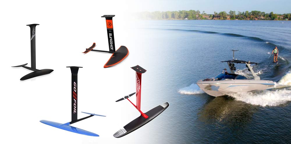
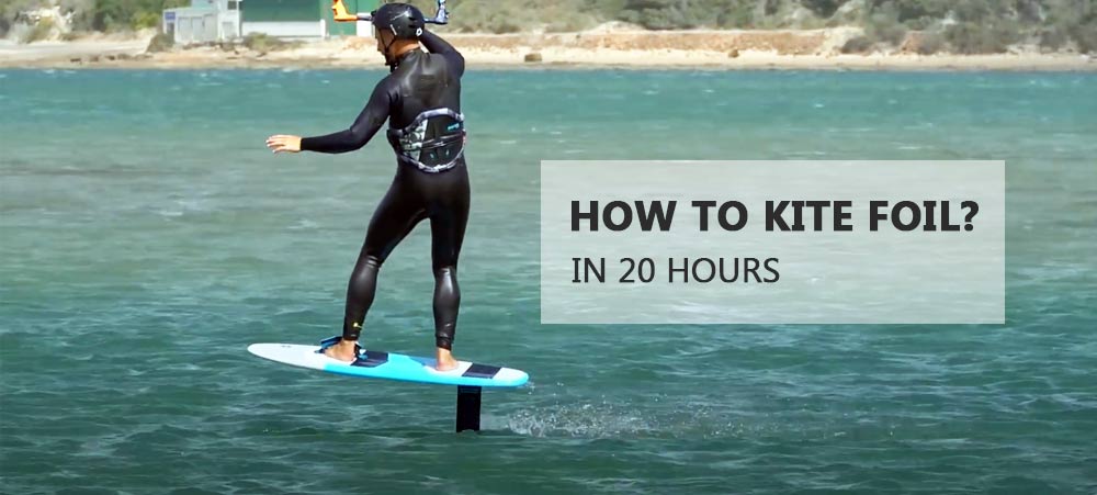
Target User Profiling: Identifying the foil’s intended purpose, whether it’s for surfing, kiteboarding, racing, wing foiling, SUP foiling, or another discipline, is crucial. This step includes defining core performance needs such as load capacity, speed, and wave resistance.
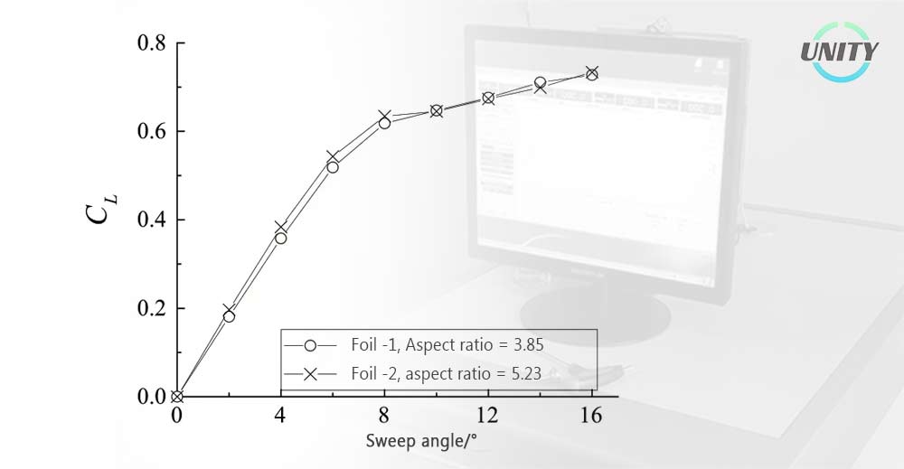
Fluid Dynamics Design: Computational Fluid Dynamics (CFD) software is employed to simulate the interaction between water flow and the foil surface. The goal is to optimize the lift-to-drag ratio (L/D Ratio), ensuring the foil performs at its best in various conditions.
Material Selection Strategy: Materials are chosen based on a balance of strength, weight, and cost. Carbon fiber (such as T700/T800), epoxy resin, and foam core materials like PVC, PU, PMI, PET, etc. are common choices for achieving the right performance characteristics.
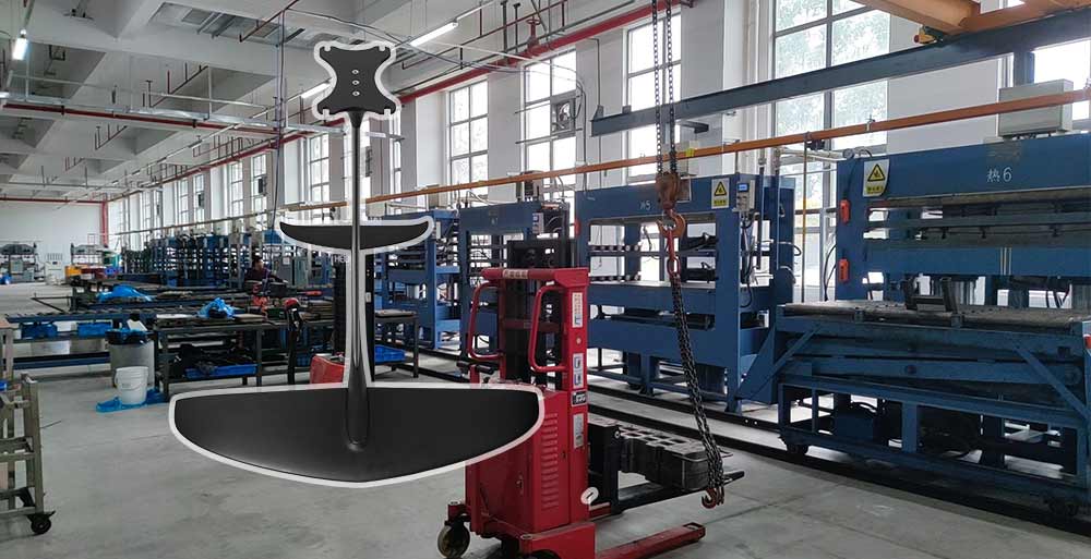
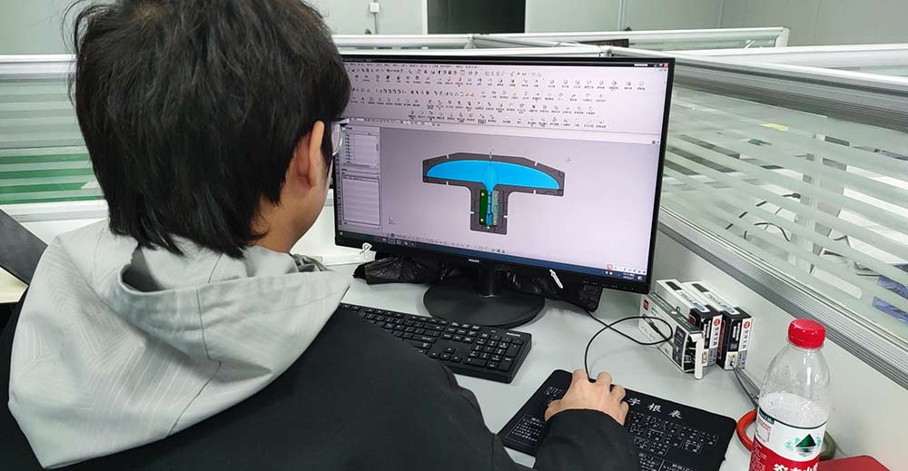
1.2 3D Modeling and Structural Optimization
Here are some references for hydrofoil building.
Front Wing Parameters: Area (500-1500 cm²), aspect ratio, and sweep angle (10°-30°) are optimized for maximum efficiency.
Stabilizer Matching: The stabilizer is typically 20%-30% of the front wing’s area and is crucial for balancing pitch moments.
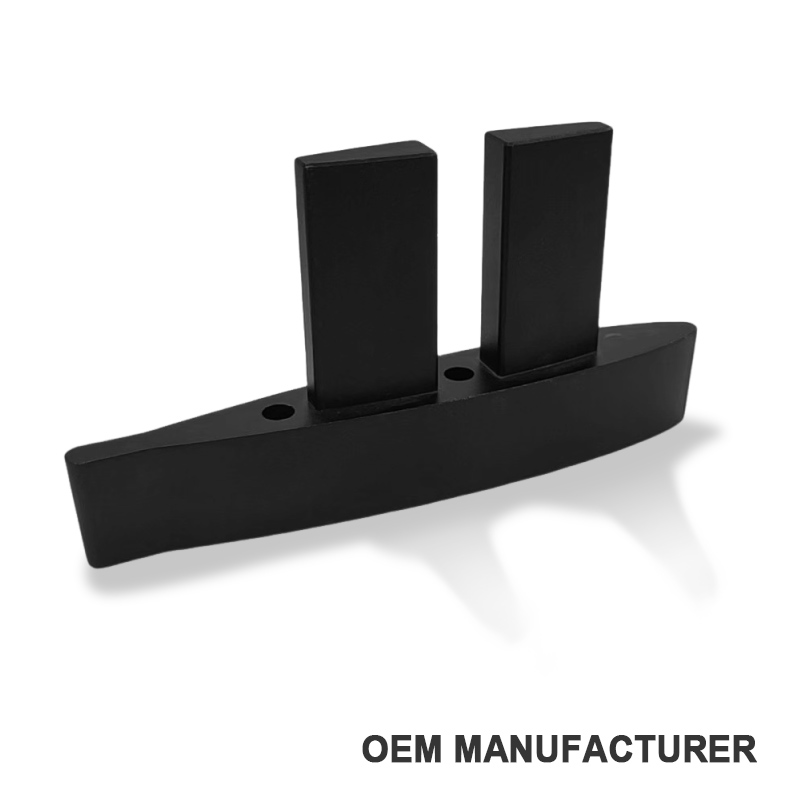
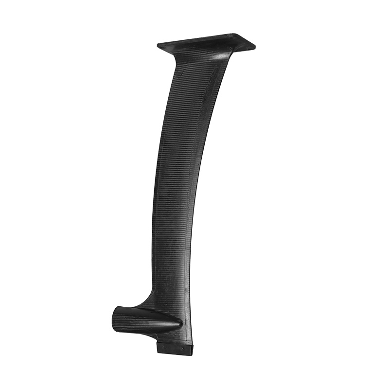
Mast and fuselage structure: Mast length (50-100 cm) and diameter (20-40 mm) are matched to ensure the necessary bending strength. The fuselage, which connects the mast to the wings, is designed for optimal rigidity and minimal drag. It typically has a streamlined shape with a length of 40-80 cm, designed to reduce water resistance and improve overall maneuverability.
Titanium bolts and carbon fiber inserts are used to ensure reliable connections. But actually, we will design to customers’ requirements.
2. Prototype Testing:
Once the design phase is completed, the next critical step is prototype testing. This stage is crucial for validating the design choices and ensuring that the hydrofoil performs as expected under real-world conditions. It involves both rapid prototyping techniques and rigorous testing to identify areas for improvement and fine-tuning before mass production. The goal is to confirm that the hydrofoil building not only meets design specifications but also delivers optimal performance and user experience in actual usage.
2.1 Rapid Prototyping
-
3D Printing Technology: To streamline the prototyping process for hydrofoil building, 3D printing is employed to produce 1:1 scale models using nylon or resin materials. This method significantly reduces costs—by as much as 60%-80%—and allows designers to quickly assess the physical form and fit of the components. 3D printed prototypes enable quick iteration of designs and can help visualize the product before committing to more expensive manufacturing methods.
-
Hand-Laminated Prototypes: In addition to 3D printing, small batches of hand-laminated carbon fiber prototypes are produced for more accurate testing of the mechanical properties and performance of the hydrofoil. These prototypes allow for hands-on evaluation of strength, rigidity, and how well the design stands up to the forces it will experience during real-world use. The carbon fiber prototypes are subjected to mechanical load tests to evaluate their performance in terms of flex, strength, and durability.
2.2 Testing Projects & Optimization Iterations
-
Towing Tank Tests: One of the key methods for evaluating the hydrofoil’s performance is towing tank testing, where the hydrofoil is submerged in controlled conditions to simulate real-world water behavior. During these tests, lift curves and stall angles (typically ranging from 12° to 18°) are carefully measured. This data helps to assess the lift-to-drag ratio and overall efficiency. High-speed cameras are also used to capture cavitation phenomena, which can negatively impact performance and lead to instability. These visual recordings provide valuable insights for refining the design and ensuring that the hydrofoil performs optimally across a range of conditions.
-
On-Water Testing: In addition to controlled testing environments, on-water trials are conducted to assess the hydrofoil’s real-world performance. During these trials, steering sensitivity is evaluated to ensure that the hydrofoil responds well to user input and provides a comfortable riding experience. The ability of the hydrofoil to resist wave impacts, a common challenge for riders, is also tested to ensure stability and control during maneuvers. Furthermore, user feedback is gathered to evaluate perceptions of weight (with a target of ≤3.5 kg) and control comfort, allowing designers to make adjustments that improve the overall handling and user experience.
3. Material Preparation and Precision Cutting
The material preparation phase plays a critical role in hydrofoil building to ensure the final product’s strength, durability, and performance. This step involves selecting and preparing the right materials, followed by precision cutting to achieve the necessary dimensions and tolerances. The use of advanced techniques such as carbon fiber cloth pre-treatment and foam core processing ensures that each component of the hydrofoil is both lightweight and highly resilient. These materials are then precisely shaped to meet the performance requirements, making them integral to the hydrofoil’s overall functionality.
3.1 Carbon Fiber Cloth Pre-treatment
-
Layering Strategy: Carbon fiber is the primary material used in hydrofoil building construction due to its high strength-to-weight ratio. In the pre-treatment phase, careful attention is paid to the direction of the fibers to ensure optimal load-bearing properties. 0° fibers, which bear the majority of the load, account for 60% of the total fiber layers, while ±45° fibers, providing shear resistance, make up the remaining 40%. This strategic layering ensures that the hydrofoil maintains both strength and flexibility where needed.
-
Prepreg Materials: Prepreg (pre-impregnated) carbon fiber cloths are used in the construction process. These materials are pre-coated with resin, which ensures precise control over the resin content, maintaining a consistency of 35% ±2%. This consistency guarantees the ideal balance between weight, strength, and durability of hydro foil building, which is essential for high-performance hydrofoils.
-
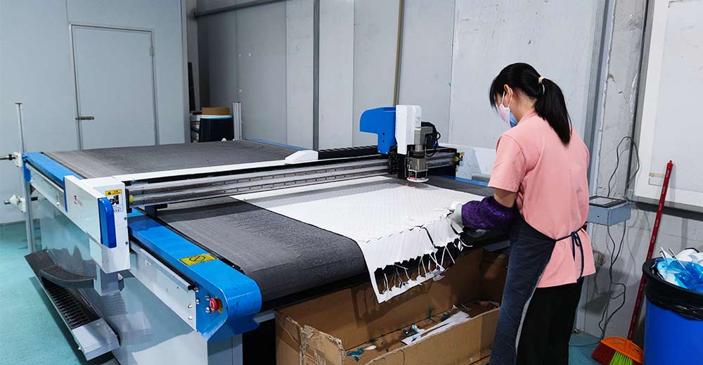
Laser Projection Cutting: To ensure precise and efficient cutting, a laser projection system is employed, with a cutting precision of ±0.1 mm. This high level of accuracy minimizes material waste and ensures that the components are cut to the exact specifications needed for optimal fit and performance. Typical layer counts for the front wing are 6-8 layers, while the mast requires 10-12 layers to ensure adequate strength and stability.
3.2 Foam Core Processing
-
Closed-Cell PVC Foam Process: To further enhance the strength-to-weight ratio, closed-cell PVC foam is used as a core material. The foaming process begins by preheating the molds to 120°C and injecting a foaming agent (such as azodicarbonamide) into the mold. The foam expands and solidifies, creating a lightweight yet durable core. The foam density is carefully controlled to 60-80 kg/m³, striking a balance between lightweight properties and sufficient compression strength (≥5 MPa), making it the ideal core material for the hydrofoil.
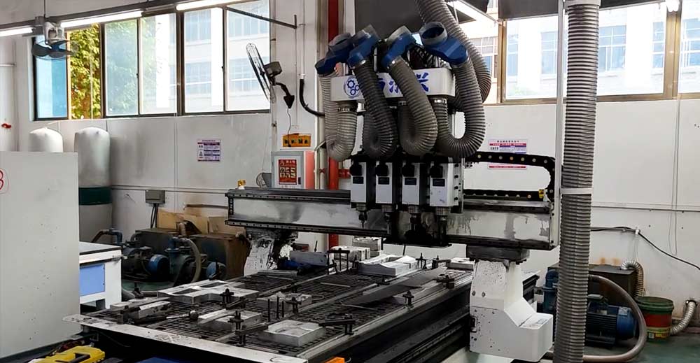
-
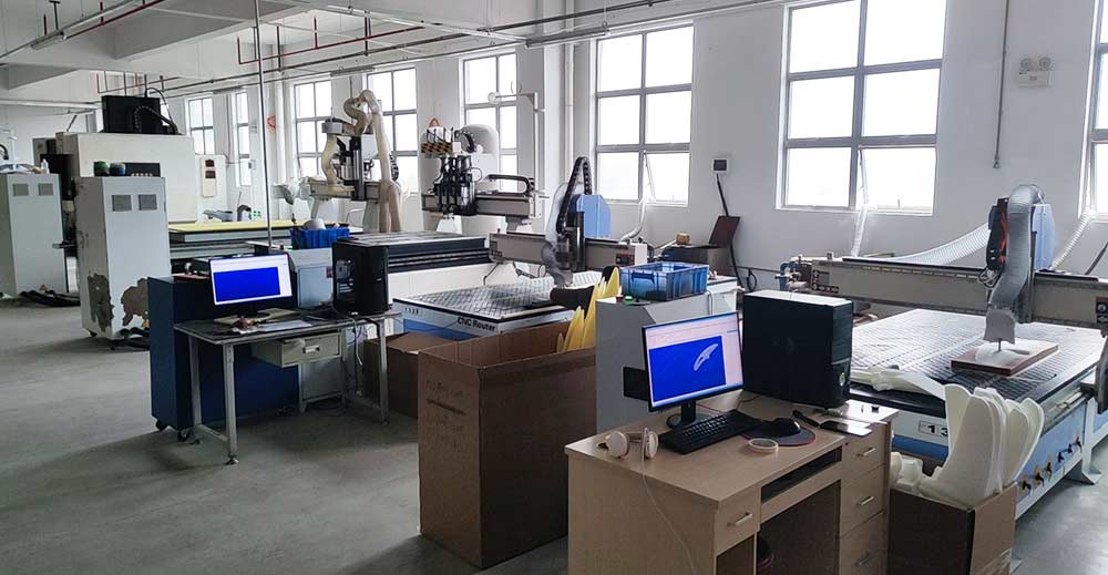
CNC Precision Machining: After the foam core is processed, it undergoes CNC precision machining. A five-axis CNC machine is used to carve the foil profile with an exceptional level of detail, achieving a surface roughness of Ra ≤ 3.2 μm. This ensures that the surface is smooth and precise, reducing drag and improving overall performance. The gap between the foam core and the carbon fiber shell is also carefully matched to 0.05-0.1 mm to ensure a perfect fit and prevent any performance loss due to misalignment.
4. Molding Process:
After the materials are prepared and the components are cut to the correct dimensions, the molding process begins. This phase is crucial for forming the final shape of the hydrofoil building, with techniques like hot molding and autoclave curing used to achieve the ideal balance of strength, rigidity, and lightweight properties. The precision in this step ensures that the hydrofoil will perform optimally in real-world conditions, with minimal risk of defects or weaknesses.
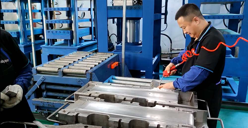
4.1 Hot Molding
-
Layering Sequence: The layering sequence begins with a release fabric, followed by layers of carbon fiber, then the foam core, additional carbon fiber layers, breathable felt, and a final vacuum bag. This sequence ensures that the foam core is fully encapsulated in carbon fiber, providing maximum strength while keeping the overall weight low.
-
Heating: Through the method of heating to create a tight, seamless bond between the layers of carbon fiber and foam, resulting in a smooth, high-quality surface that is free from imperfections. The pressure also helps to remove excess resin, ensuring a consistent and optimal resin content throughout the laminate.
-
Colding: The curing process consists of two stages. In Stage 1, the temperature is raised to 80°C for 2 hours to initiate resin gelation, allowing the layers to bond together. In Stage 2, the temperature is increased to 120°C for 4 hours, completing the crosslinking reaction and ensuring that the resin fully hardens, resulting in a solid, durable component.
4.2 Autoclave Curing (For Premium Models)
-
Pressure and Temperature Control: For premium hydrofoil models, an autoclave curing process is used. In this process, the hydrofoil is subjected to a pressure of 6-8 bar and a high temperature of 150°C. This pressure and temperature combination helps to enhance the density of the carbon fibers, resulting in a more compact, stronger structure.
-
Porosity Rate: One of the key benefits of autoclave curing is its ability to achieve a lower porosity rate compared to vacuum bag molding. While the vacuum bag molding method typically yields a porosity rate of 2%-3%, the autoclave process results in a porosity rate of ≤1%. This ensures that the final product is more dense and less prone to structural weaknesses, making it ideal for high-performance applications.
Generally, the autoclave is used to build hydrofoils with a big size.
5. Rough Shape Precision Finishing
After the initial shaping of the hydrofoil components, the next crucial step is precision finishing for hydrofoil building. This phase ensures that the surfaces meet exact specifications and have the desired finish quality. By using advanced CNC roughing techniques followed by hand polishing, the final product achieves millimeter-level accuracy and a smooth, high-performance surface.
5.1 CNC Roughing
- Tool Path Planning: The rough shaping process begins with a ball-end mill, typically 6 mm in diameter, which is used to remove excess material. The mill cuts to a depth of 0.5 mm per pass, ensuring precise and efficient material removal. The cutting paths are carefully planned to optimize the machining process and minimize the risk of defects or material waste.
- Manual Finishing Margin: A 0.2 mm margin is left after CNC roughing, allowing for manual finishing. This ensures that the final shaping will be accurate and free of machining marks, providing a smooth surface ready for finer polishing.
5.2 Hand Finishing
- Sanding Strategy: The hand-finishing phase focuses on refining the surface to achieve the desired smoothness and finish. The sanding process begins with coarse grit (80-120 grit) to remove any prominent bumps or imperfections from the surface. Once the surface is relatively smooth, fine sanding with 240-400 grit is performed to further smooth out any remaining inconsistencies.
- Mirror Finishing: To achieve a flawless finish, a mirror polishing process is employed. This involves using grits ranging from 1000-3000 and applying a polishing compound to achieve a surface roughness of Ra ≤ 0.8 μm. The result is an ultra-smooth, high-quality surface that reduces drag and enhances the hydrofoil’s performance in the water.
6. Coating and Surface Treatment
Coating and surface treatment are essential steps for making a hydrofoil, which enhances the foil’s durability, appearance, and resistance to environmental factors. These processes protect the material and ensure the hydrofoil maintains its performance over time.
6.1 Primer and Filling
- Epoxy Primer Coating: The primer layer is applied with a thickness of 30-50 μm, designed to fill microscopic pores in the surface. This coating improves adhesion for subsequent layers and provides an additional protective barrier.
- Curing Process: To accelerate the curing of the epoxy primer, the part is baked at 80°C for 30 minutes. This step ensures that the primer fully cures, providing a strong foundation for the next layers.
6.2 Pattern Design and Spraying
- Water Transfer Printing: For aesthetic and functional purposes, water transfer printing is used to apply intricate patterns or designs to the hydrofoil surface. The foil is immersed in an activator bath maintained at 25°C, while the transfer film is stretched to 120%-130% to ensure proper coverage and adhesion.
- Polyurethane Clear Coat: A multi-layer polyurethane clear coat is applied over the printed surface. The total coating thickness is ≥100 μm, providing an additional layer of protection against abrasion, UV radiation, and water exposure.
7. Quality Control: Zero-Defect Management System
Quality control is an integral part of the manufacturing process, ensuring that every hydrofoil meets the highest standards of performance and durability. Through a combination of non-destructive testing (NDT), destructive sampling, and thorough inspection, any potential issues are detected and addressed before the product reaches the customer.
7.1 Non-Destructive Testing (NDT)
- Ultrasonic Testing: Ultrasonic testing is used to detect delamination or internal defects with a resolution of 0.5 mm. The acceptance standard requires that defect areas must be smaller than 5 mm² and should not be continuous, ensuring that the hydrofoil maintains structural integrity.
- X-Ray Imaging: X-ray imaging is employed to identify any internal bubbles or inconsistencies in the material. If a density difference of >3% is detected, the part is deemed non-compliant and removed from production to maintain quality standards.
7.2 Destructive Sampling
- Three-Point Bending Test: To evaluate the strength of the hydrofoil, a three-point bending test is performed at a loading rate of 5 mm/min. The fracture energy is recorded, and a minimum value of ≥50 J is required for acceptance.
- Salt Spray Test: A 5% NaCl solution is sprayed on the hydrofoil for 96 hours to simulate long-term exposure to corrosive environments. The part must pass this test without showing visible corrosion spots, ensuring its resistance to saltwater and other harsh conditions.
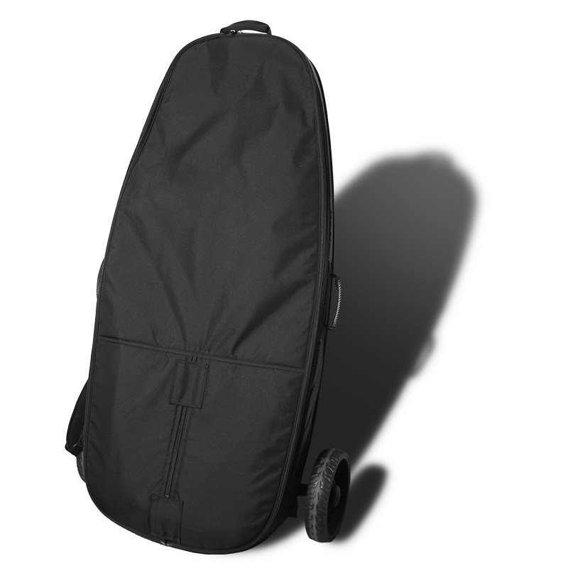
8. Packaging and Delivery
Once the hydrofoil passes all quality checks, it moves on to the packaging and delivery stage. Proper packaging protects the product during transportation, while traceability systems ensure the product’s history and authenticity are maintained.
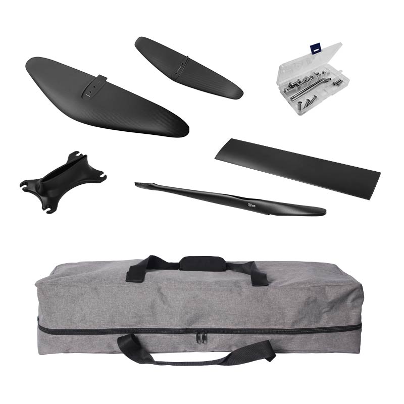
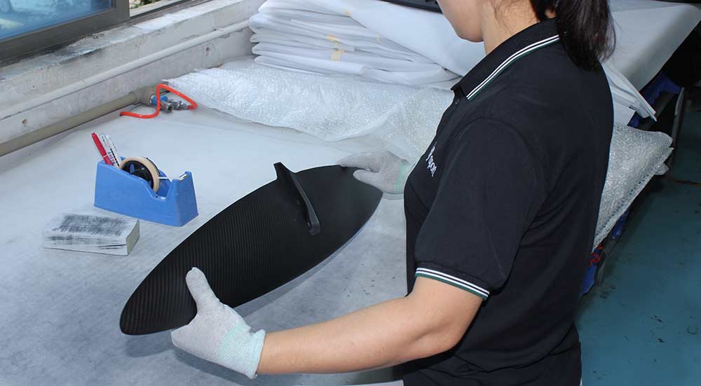
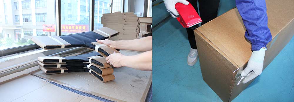
8.1 Customized Protective Packaging
- EPE Foam Molds: Custom CNC-cut EPE foam molds are used to securely package the hydrofoil. The foam molds are designed to match the shape of the hydrofoil and are at least 30 mm thick, offering excellent protection during shipping. Impact tests have shown that the hydrofoil remains undamaged after a 1.2-meter drop, ensuring safe delivery.
- Moisture Control: To prevent moisture damage during transit, silica gel desiccants are included in each package, with a minimum of 20 g/m³ per box volume. This helps to maintain the product’s integrity in varying environmental conditions.
8.2 Traceability System Integration
- Laser Marking QR Codes: Each hydrofoil is marked with a laser-engraved QR code containing essential information, such as the production batch, material composition, and the quality inspector’s code. This provides transparency and traceability throughout the manufacturing process.
- Cloud-Based Data Storage: All data related to the hydrofoil’s production is stored in a cloud database, enabling a traceability period of up to 10 years. This allows for easy access to historical records, supporting long-term product quality assurance.
9. Continuous Improvement: Data-Driven Process Upgrades
Continuous improvement is at the heart of maintaining product excellence. By monitoring production data and incorporating user feedback, the manufacturing process is constantly optimized to achieve higher performance and efficiency.
9.1 Production Data Monitoring
- Statistical Process Control (SPC): Key production parameters, such as curing temperature (within a ±2°C tolerance), are continuously monitored to ensure that they meet the required specifications. A CPK value of ≥1.33 is targeted for these critical parameters.
- Real-Time Alarm Systems: In order to maintain consistent quality, real-time alarm systems are implemented to detect any deviations beyond the set limits. If any parameters exceed acceptable thresholds, production is automatically halted to prevent defects.
9.2 User Feedback Loop
- Failure Mode Analysis: A Failure Mode and Effects Analysis (FMEA) process is used to analyze potential issues based on feedback from the field. For example, if cracks occur in the front wing, the analysis may lead to optimizing the layer angles to prevent future failures.
- Annual Upgrade Plans: The company has established an annual upgrade cycle, typically between 18-24 months, with performance improvements of at least 15%. This ensures that the hydrofoil’s design and manufacturing processes evolve with advancements in materials and technology, continually enhancing the product’s performance and reliability.
By rigorously controlling these 9 major steps and 37 sub-processes, a modern foil factory can maintain a defect rate of less than 0.3%, while achieving a perfect balance between performance and cost. From fluid dynamics calculations to the final step of packaging protection, every detail exemplifies the precision and beauty of industrial manufacturing.
Hydrofoil Build Conclusion
Producing a high-quality hydrofoil is a complex and precise process that requires attention to detail at every stage, from design to packaging. By adhering to scientific design principles, precise manufacturing processes, and rigorous quality control measures, manufacturers can build hydrofoils that are both durable and high-performing. This ensures that the final product meets the needs of its intended application and provides exceptional performance in the field.
This comprehensive guide has taken you through the entire process of hydrofoil building, from the initial design stage to the final packaging and delivery. If you have any further questions or would like to learn more about a specific aspect of hydrofoil production, feel free to reach out!